
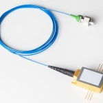

Converting an optical signal into an electrical signal is a critical step in microwave photonics, radar systems, optical communications, and high-frequency test equipment. The performance of this conversion directly affects measurement accuracy, signal integrity, and the usable frequency range of the entire system.
Selecting a detector based only on its maximum bandwidth can lead to disappointing results. Engineers must also consider responsivity, optical input power, RF output characteristics, impedance matching, and the operating wavelength. Understanding these parameters helps identify a detector that meets the actual requirements of the application rather than simply offering an impressive headline specification.
1. Start with the Required Frequency Range
Bandwidth is one of the first parameters to evaluate when selecting a high speed photodetector. It describes the frequency range over which the detector can convert optical modulation into an electrical output with an acceptable response.
For example, NEON's HSPD product family includes configurations with small-signal bandwidths extending to 30 GHz, depending on the model. The appropriate version depends on the frequency range of the signal being measured and the performance of the surrounding RF equipment. Engineers can review the HSPD high-speed InGaAs photodetector specifications to compare available configurations.
A practical selection process should consider three questions:
- What is the highest frequency component that must be measured?
- How much amplitude variation is acceptable across the operating band?
- Does the system require additional bandwidth for waveform analysis or future upgrades?
A detector that barely meets the required frequency limit may leave insufficient margin for accurate characterization. The entire optical-to-electrical measurement chain should therefore be evaluated.
2. Evaluate Responsivity and Optical Power
Responsivity, expressed in amperes per watt (A/W), describes the photocurrent generated per unit of incident optical power under specified conditions. Higher responsivity can improve signal strength, but it does not automatically guarantee better system performance.
The wavelength must be considered alongside responsivity because a detector's sensitivity varies across its response range. NEON's InGaAs products cover telecommunications-related wavelengths, with exact specifications depending on the detector model.
Optical input power is equally important. A detector designed for weak signals may not be suitable for an application with a powerful laser source. Engineers should compare the expected optical power with the specified operating and saturation limits. They should also examine the RF output level to determine whether the signal can be measured without distortion.
For demanding applications, leave sufficient operating margin rather than designing around the maximum permissible input.
3. Understand the Importance of RF Matching
A detector's electrical output must connect effectively to amplifiers, spectrum analyzers, oscilloscopes, or other RF instruments. Impedance mismatch can cause reflections, frequency-response irregularities, and measurement errors.
Many NEON detector modules provide 50-ohm RF outputs and connectors such as SMA or 2.92 mm, depending on the model. These interfaces are commonly used in RF and microwave measurement systems. However, connector compatibility alone does not guarantee a well-matched measurement chain.
A complete evaluation should include:
- RF output impedance and voltage requirements.
- Connector type and frequency rating.
- Output voltage or power limits.
- Cable loss and connector quality.
- The frequency response of downstream instruments.
These details are essential to effective high speed photodetector design, especially when measurements extend into the microwave range.
4. Select the Right Detector Architecture
A standard high-speed detector may be sufficient when the system requires optical-to-electrical conversion without additional gain. Other applications may benefit from an amplified detector module that integrates electrical amplification, or a balanced detector that subtracts two optical signals.
The correct architecture depends on the measurement objective. Amplification may simplify system integration, but it also introduces considerations such as noise, gain flatness, and output saturation. Balanced detection can suppress common-mode noise when the optical paths and detector channels are appropriately matched.
Rather than choosing a more complex detector by default, engineers should identify the main system limitation first.
5. Verify Specifications Under Real Operating Conditions
Before purchasing, request the relevant datasheet and confirm bandwidth, responsivity, wavelength range, optical power limits, output impedance, supply voltage, and operating temperature. Where necessary, request measured frequency-response curves and clarify the conditions under which the specifications were obtained.
NEON provides high-speed detector solutions for optical communications, radar information processing, electronic warfare, and high-speed signal testing. Its high-speed photodetector product range is a useful starting point for comparing device options.
Conclusion
Choosing a suitable detector requires balancing bandwidth, sensitivity, optical power handling, and RF compatibility. A systematic evaluation helps engineers avoid unnecessary cost while preserving measurement accuracy and system reliability.
For application-specific requirements, contact NEON with the operating wavelength, target frequency range, expected optical input power, and RF interface requirements. These details provide a practical basis for identifying an appropriate detector configuration.